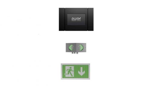
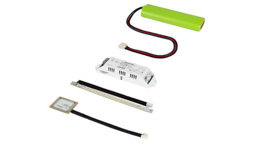
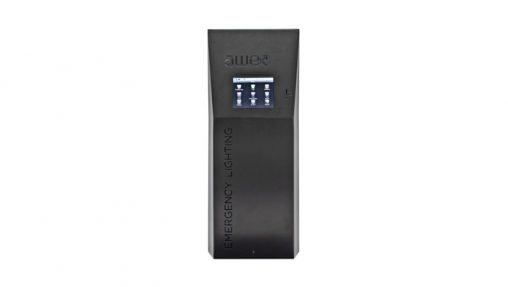
designing the device, all applicable standards were followed. The device is composed of an inverter which serves to maintain the voltage of 230 VAC ± 3 % 50 Hz on output circuits. The system is equipped with batteries whose capacity is dependent upon load and emergency luminaire supply period.
The batteries are self-operating accumulators with a 10-year operation life. SPS is based on the Offline technology, connected devices are supplied directly from the mains. The supply voltage is regularly monitored and in the event of a loss, the control system (after ca. 150 ms) disconnects the mains power and switches into accumulator mode. The device is secured against extensive load and short circuit. The circuit safety devices are continuously monitored and the damage notification is displayed on the front signaling panel. In spite of the simple structure, SPS has been provided with a set of modern functions. The unit can be configured and operated by means of the built-in www server and SmartVisio app (optional). The use of all-purpose Modbus and BACnet protocols allows integrating system from BMS. A small size of the cabinet allows installing the system in places where large-size central battery systems do not fit.
The key parameters of the Central Battery System SPS:
• Compliance with the following standards: EN 50171, EN 50272-1, EN 50272-2, EN 60950-1
• Measuring voltage and current of battery charging/discharging
• Monitoring circuit safety devices
• Built-in internal power supply loss sensor with a switch point in compliance with EN
60950-2-22
• 4 potential-free inputs configurable as a switch, phase cancellation sensor, interlock
• 4 voltage inputs configurable as a switch, phase cancellation sensor, interlock
• 4 potential-free outputs configurable as the mains operation indicator, battery-based
operation, defects, emergency operation, interlock, test, etc.
• Protection against serious battery discharge
• Configuration and operation through the built-in www Server and SmartVisio app
• MODBUS and BACNET protocol support
• Configuration of non-maintained operation, maintained operation, switchable operation
• Possible to set any work modes, phase cancellation sensors and support time
• Remote configuration import and export, access to logs and updating software
• Possible to send e-mails automatically
• Functional test (short) and support test (long) automatically or manually activated
• Supporting many languages
• Programmable late switch into emergency mode and return from this mode
• Casing indicators: mains operation, battery-based operation, emergency operation,
interlock, test, charger failure, battery failure, inverter failure, circuit failure, protection
against serious discharge
• Casing buttons: short/long test start, protection against serious discharge reset


