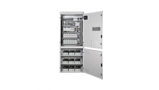
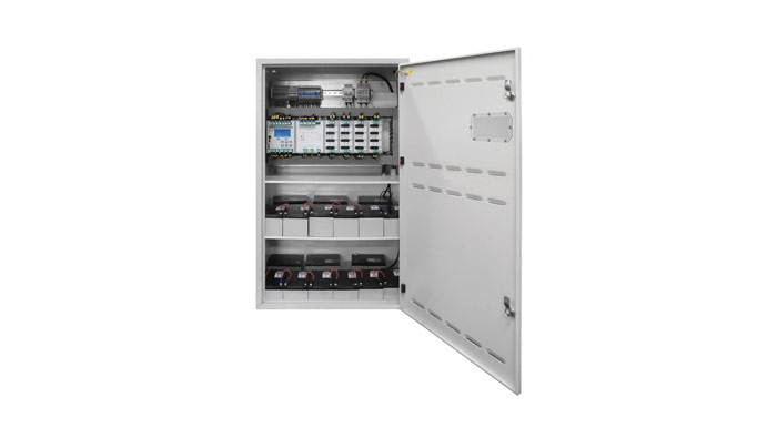
აღწერა
The system enables emergency supplying of the fittings with a total power of 1500W for the time of 1h, or the fittings 500W – for 3h. With four sensor inputs installed in the steering module it is possible to control fire zones through the use of sensors decay phases (CFZ), which control power supply to the switch board of power supply zone. In addition, the system can be expanded by ELS-230 modules, with nine voltage control inputs. Linear modules have separate protection for AC and DC mode, this significantly increases the safety level of switching the emergency mode in the building. In the emergency mode, the system works in IT network (isolated system).
The most important parameters:
• LCD display with easy-to-use menu
• Automatic test performing
• Automatic detection and adding luminaires to the system
• Monitoring of each luminaire
• Monitoring of each circuit
• Programming and configuration of the luminaires directly from the central unit
• Communication with luminaires through the power cable
• SMART technology – any mode of operation of the luminaire
• The linear modules are secured for the AC and DC mode separatelly
• SD card slot and card itself allow to save the periodic test results, event log and system configuration
• Possibility to record the back-up of the system on the SD card
• Night mode operation
• Possibility to control luminaires and functions of the system through the 24V and 230V internal and external connectors
• Possibility to monitor power in the distribution boards and in the separate lighting circuits
• USB slot
• RJ45 connector for direct communication with any computer via Ethernet
• Preview of the system via any web browser
• Management and visualization of the system by using dedicated software SMART VISIO
• Supply of the fixtures of total capacity 1500W for time 1h or 500W for 3h


CM-NET CONTROL MODULE
The CM-NET control module supervises and manages other modules
included in the central battery system.
Features:
Configuration:
• Eight configuration keys
• SD card
• RJ45 connector for SMART VISIO
System control:
• Four 24V potential-free inputs that can be programmed for: functional
test, battery test, sensor input etc.
• Four function keys:
• Lock
• Functional test activation
• Battery test activation
• Deep discharge error reset
• Four programmable function keys:
• Switching circuits for AC power supply
• Switching circuits for DC power supply
• Alarm reset: leakage fault
• Alarm reset: emergency mode
• Functional test without preheating
• Three LON communication buses
• 2 timers
• 3PH phase loss sensor connector
• Remote system lock input
External communication:
• Current system status indication
• LED indicators
• LCD display
• BMS – BACnet, LonWorks
• Three potential-free outputs for PZS or BMS

L-980 CHARGER UNIT
The charger module ensures battery charging on the basis of UI characteristic with temperature compensation according to PN-EN 50171. The charging algorithm of the charger is supervised by the control module. The charger is equipped with an internal active PFC module, which guarantees that the power factor is close to 1.0 (λ≈1).
The charger is used for charging batteries with the voltage rated at 216V.
The maximum power of the charger is 980W. If a larger capacity battery
needs to be charged, the BST-980 booster is used.
Features:
Basic:
• Charging battery packs as required by PN-EN 50171
• Supporting and controlling the BST-980 charge booster
• Monitoring leakage conductance in branch circuits
• Protection against deep discharge
• Battery voltage symmetry monitoring
• Fan control
• Three connectors for the measurement of:
• voltage
• current
• temperature
External communication:
• Displaying the current status of the charger
• Four programmable potential-free outputs
• Battery charge indicator LED
• Service pin

CCM CHARGING CONTROL MODULE
CCM module is responsible for accumulators charging process. Charging process is realized by BST – 430W booster. It’s possible to use larger accumulators by increasing quantity of BST – 430W booster, up to 16 pcs.
Features:
• Supporting and controlling the BST-430 charge booster
• Monitoring leakage conductance in branch circuits
• Protection against deep discharge
• The ability to control individual batteries in cooperation with BC battery control system
• Fan control
• Two connectors for the measurement of:
• current
• temperature
• RS interface for communication with the BC system
• Displaying the current status of the charger
• Three programmable potential-free outputs
• Status indicator LED

BST 430 – BOOSTER
The Booster module ensures battery charging on the basis of UI characteristic with temperature compensation according to PN-EN 50171. The charging algorithm of the charger is supervised by the control module. The charger is equipped with an internal active PFC module, which guarantees that the power factor is close to 1.0 (λ≈1). The booster is used for charging batteries with the voltage rated at 216V. The maximum power of the charger is 430W.

ML-E 2X6A CIRCUIT MODULE
The 2x6A module supplies power to one branch circuit.
Features:
• Controlling SMART luminaires
• Monitoring up to 20 luminaires per circuit
• Unique addresses programmed during production process
• Freely programmable work mode
• Independent control of each circuit
• Independent control of each luminaire
• Identification of each luminaire
• Fault, module status and circuit status indicators
• Service pin
• Supplying luminaires with PN-EN 60347-2-7 ballasts and luminaires with LED and incandescent light sources
• Adjustable AC/DC changeover time

ML-E 4X3A CIRCUIT MODULE
The 4x3A module supplies power to two branch circuits.
Features:
• Controlling SMART luminaires
• Monitoring up to 20 luminaires per circuit
• Unique addresses programmed during production process
• Freely programmable work mode
• Independent control of each circuit
• Independent control of each luminaire
• Identification of each luminaire
• Fault, module status and circuit status indicators
• Service pin
• Supplying luminaires with PN-EN 60347-2-7 ballasts and luminaires with LED and incandescent light sources
• Adjustable AC/DC changeover time
• Adjustable emergency duration for each circuit

ML-E 8×1,5A CIRCUIT MODULE
The 8×1,5A module supplies power independently to four branch circuits.
Features:
• Controlling SMART luminaires
• Monitoring up to 20 luminaires per circuit
• Unique addresses programmed during production process
• Freely programmable work mode
• Independent control of each circuit
• Independent control of each luminaire
• Identification of each luminaire
• Fault, module status and circuit status indicators
• Service pin
• Supplying luminaires with PN-EN 60347-2-7 ballasts and luminaires with LED and incandescent light sources
• Adjustable AC/DC changeover time
• Adjustable emergency duration for each circuit

ML-S 1X6A CIRCUIT MODULE
The 1x6A module supplies power to one branch circuit.
Features:
• Controlling SMART luminaires
• Monitoring up to 20 luminaires per circuit
• Flexible programming of circuit operation modes
• Independent control of each circuit
• Independent control of each luminaire
• Separate protection of AC mains and DC battery power supply
• Fault, module status and circuit status indicators
• Service pin
• Supplying luminaires with PN-EN 60347-2-7 ballasts and luminaires with LED and incandescent light sources
• Adjustable AC/DC changeover time

ML-S 2X4A CIRCUIT MODULE
The 2x4A module supplies power to two branch circuits.
Features:
• Controlling SMART luminaires
• Monitoring up to 20 luminaires per circuit
• Flexible programming of circuit operation modes
• Independent control of each circuit
• Independent control of each luminaire
• Separate protection of AC mains and DC battery power supply
• Fault, module status and circuit status indicators
• Service pin
• Supplying luminaires with PN-EN 60347-2-7 ballasts and luminaires
with LED and incandescent light sources
• Adjustable AC/DC changeover time
• Adjustable emergency duration for each circuit

ML-S 4x3A CIRCUIT MODULE
The 4x3A module supplies power independently to four branch circuits.
Features:
• Controlling SMART luminaires
• Monitoring up to 20 luminaires per circuit
• Flexible programming of circuit operation modes
• Independent control of each circuit
• Independent control of each luminaire
• Separate protection of AC mains and DC battery power supply
• Fault, module status and circuit status indicators
• Service pin
• Supplying luminaires with PN-EN 60347-2-7 ballasts and luminaires
with LED and incandescent light sources
• Adjustable AC/DC changeover time
• Adjustable emergency duration for each circuit

LS-24 SENSOR MODULE
This potential-free input module monitors up to 8 inputs in a 24V current loop. The inputs enable selective activation of luminaire control groups by assigning phase loss sensors to them. In the event of a voltage loss at the primary lighting switchboard, luminaires with control groups assigned to them are activated.
The inputs can also be used as potential-free inputs for building management systems (BMS) to activate individual control groups. The system can integrate up to 10 modules of the LS-24 and LS-230 type.
Features:
• Monitoring of the phase loss sensor current loop
• Monitoring of the 24V DC current loop
• Possibility of joint control with a BMS via potential-free inputs
• Programmable recovery delay
• Service pin
• Fault and module status indicators
• Active input indicators
• Possibility of sensor input negation

LS-230 SENSOR MODULE
The module has eight 230V AC potential-free inputs. It enables setting up emergency luminaire control groups with the power supply of primary lighting circuits. The logic of the inputs can be inverted, so that the input is in active state at 0V and inactive at 240V. This functionality enables monitoring of individual protections of the primary lighting system. The inactive state recovery delay time is programmable within the range of 1 second to 1 hour. The system can integrate up to 10 modules of the LS-24 and LS-230 type.
Features:
• Monitoring of primary lighting switches
• Programmable inversion of input logic
• Possibility of monitoring individual primary lighting protections
• Programmable recovery delay time
• Service pin
• Fault and module status indicators
• Input status and inversion indicators

ELS-230 EXTERNAL MODULE
The ELS-230V sensor module is used for monitoring of 230V AC potential signals from primary lighting switches in order to activate an emergency luminaire control group along with the primary lighting. The module has 9 inputs. The inputs can be inverted to monitor individual circuit protections. The ELS-230 module can also serve as a phase loss sensor. The control inputs can be assigned the recovery delay function. The module has a service pin, rotary address selector switches, a LON connector for data transmission (with a built-in terminating resistor) and a 24V power supply connection. The module is also equipped with LED indicators displaying the current logic settings and the status of individual inputs.
Features:
• Monitoring of primary lighting switches
• Function of a phase loss sensor
• Programmable inversion of input logic
• Possibility of monitoring individual primary lighting protections
• Programmable recovery delay time
• Service pin
• Fault and module status indicators
• Input status and inversion indicators

CZF LON EXTERNAL MODULE
The CZF LON sensor module is used for monitoring of 230V AC potential signals from primary lighting switches in order to activate an emergency luminaire control group along with the primary lighting. The module has 3 inputs. The inputs can be inverted to monitor individual circuit protections. The CZF LON module can also serve as a phase loss sensor. The control inputs can be assigned the recovery delay function. The module has a service pin, rotary address selector switches, a LON connector for data transmission (with a built-in terminating resistor) and a 24V power supply connection. The module is also equipped with LED indicators displaying the current logic settings and the status of individual inputs.
Features:
• Monitoring of primary lighting switches or functioning asa phase loss sensor
• Programmable inversion of the action logic of individual inputs
• Possibility of monitoring individual primary lighting protections
• Programmable recovery delay time
• Service pin
• Fault and module status indicators
• Input status indicators

CZF-01 PHASE LOSS SENSOR
The quick-acting phase loss sensor is used for voltage monitoring in primary lighting switchboards to energise specific circuits or the whole system for emergency operation. The switching threshold is as specified in PN-EN60598-2-22.
Features:
• Phase loss detection
• Switch activation detection
• Switchover threshold as per PN-EN 60598-2-22
• Delay time <200 ms
• Mounting in DIN-3 rail

PZS LON MODULE
The PZS LON module is used for monitoring of Central Battery Systems connected via LON buses. Thanks to the PZS LON module the user can check the name and the status of the connected system. Additionally, all faults and errors that have occurred in each of the connected systems can be viewed.
The module has an LCD display and LEDs indicating: AC operation, DC operation, Lock, Fault; the panel is equipped with 5 push-buttons and key.
Features:
Wall-mounted
• Reading and viewing the current status of all systems connected to the module
• Plug & Play device – no configuration required
• System monitoring within a single group (up to 10 systems); selection of 1-4 groups
• Possibility of locking all connected system components by pushing the Block button
• Configurable lock for selected systems (not all systems have tobe locked by the module; monitoring only possible)
• Configuration is saved when the power supply is interrupted
• Loss of communication is notified by the module (timeout)
• Loss of communication with the system removes any previously applied locks
• Acoustic signalling of system faults or errors (can be postponed for a specific time)
• LED indicators on the front panel: AC supply mode, DC supply mode, Lock, Fault
• LED status depends on all monitored systems